SETTINGS
Appearance
Language
About

Settings

Select a category to the left.

Appearance

Theme

Light or dark? Choose how the site looks to you by clicking an image below.

Light Dark

Language

Preferred Language

All content on utk.claranguyen.me is originally in UK English. However, if content exists in your preferred language, it will display as that instead. Feel free to choose that below. This will require a page refresh to take effect.

About

"utk.claranguyen.me" details

Domain Name: claranguyen.me
Site Version: 3.0.1
Last Updated: 2019/08/18
Getting Started

Synopsis

  • Read the lab writeup on Canvas.
  • This lab is due on September 26, 2017 at 23:59:59.

Requirements

  • Arduino Due
Synopsis
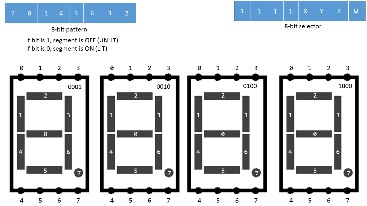
Now it's back to using the Arduino Due. We are going to (finally) start playing around with the number display on the Arduino Due's shield. We call it the 7-segment display. Here is a diagram of it (which I casually stole from the lab writeup on Canvas):


Your goal is to write a program that will allow you to type in a number in the Serial Monitor, and it will display that number on the 7-segment display.

What is given to you

  • Code to read input and parse numbers
  • A bunch of useful comments on how to implement everything
You will write what is missing in lab5stud.ino. This includes the values of the DIGITS[] and SEGMENTS[] variables at the top of the file, the SetupPins() function, and the SetSegment() function.
How to generate the DIGITS[] array
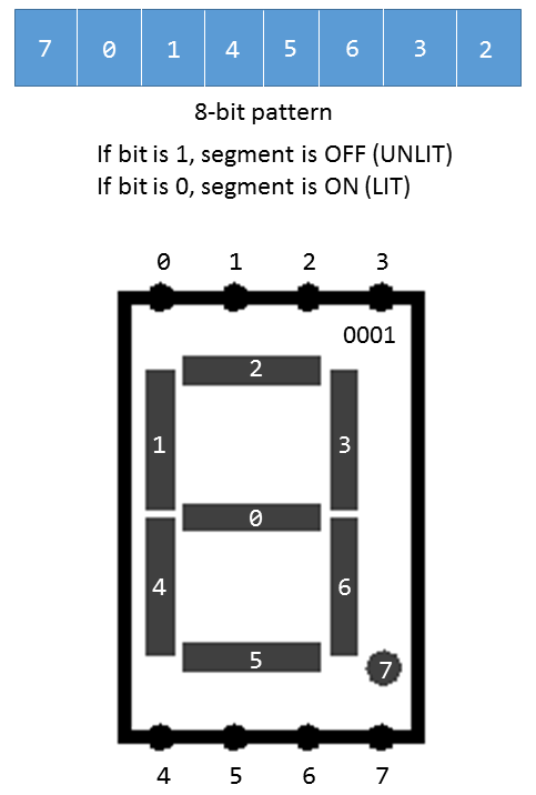
The DIGITS[] array is not as intuitive as SEGMENTS[] (where you literally copy it off of the diagram in the previous section). Let's look at the diagram of just one of the segments, along with the pattern string.


The first thing you notice is that disgusting "70145632" array. Notice down below in the gray boxes how they are numbered. When lighting up values on the display, you simply set a specific bit to 0 and it'll light up.

Let's say you wanted to light up the number 7. Look at the diagram of gray boxes. You will see that you want to have 2, 3, and 6 lit up. So let's set it up. Set the ones that you do not want lit to be 1. Set the ones you want lit to be 0.
PATTERN  7 0 1 4 5 6 3 2
TO LIGHT 1 1 1 1 1 0 0 0
Therefore, the number "7" is represented by the binary number 0b11111000 (0xF8)! Now calculate the others.
Simulator: Binary2Segment
Because I am a nice person, I have written a simulator that'll allow you to plug in binary numbers and it'll show you what it'll look like. Type in a number and click "Show". It'll light up the bits you want.

Binary Input (without "0b")


Segment Display

Setting up Inputs in Arduino
Inputs and Outputs don't just simply "work" in Arduino (of course...). There are a few functions that you must use to specify whether something is input or output. We will show you one, because it's all you need. Behold:
  • pinMode(pin, mode) - Configures a pin on the board to behave as either an input or an output. Here is the documentation for pinMode().
So let's say that you wanted to enable a pin (One from the Lab actually)... you'd do the following:
Code (C++)
const int CLK_DIO = 7;

void setup() {
	pinMode(CLK_DIO, OUTPUT);
}
Outputting data to Arduino
Now time for the painful part. When you have defined your SEGMENT[] and DIGIT[] variables, you will then be able to write SetSegment(). This function will take those values and "magically" make a number appear on the Arduino's 7-segment display. However, how exactly does it work?

Dr. Marz was nice enough to give you some comments to literally tell you how to do it:
Code (C++)
void SetSegment(int segment, int digit) {
  //Set <segment>'s value to <digit>

  //DO NOT USE shiftOut() in this code!!!
  //Steps to write a value
  //1. Open the latch (LATCH_DIO) by setting it's value LOW using digitalWrite()
  //2. Write the first bit to DATA_DIO, cycle the clock (CLK_DIO) using digitalWrite()
  //3. ... Write the nth bit, cycle the clock using digitalWrite()
  //4. Close the latch (LATCH_DIO) by setting it's value HIGH using digitalWrite()
}

Why you are not allowed to use "shiftOut"

Here's what the function would look like if you used shiftOut.
Code (C++)
void SetSegment(int segment, int digit) {
	digitalWrite(LATCH_DIO,LOW);
 	shiftOut(DATA_DIO, CLK_DIO, MSBFIRST, DIGITS[digit]);
 	shiftOut(DATA_DIO, CLK_DIO, MSBFIRST, SEGMENTS[segment]);
 	digitalWrite(LATCH_DIO,HIGH);
}
It is way too easy when done this way. shiftOut does all of the handling of the CLK_DIO and DATA_DIO variables for you.

Hint: You can copy and paste this function to test and make sure that your SEGMENT[] and DIGIT[] array values are correct. Just make sure you don't turn in your lab with it (or else)!

"Ok Clara, then what should I do?"

Write it manually, of course! Keep the LATCH_DIO code from above (he literally tells you to do this in the instructions). Then loop through the 8 bits given in DIGITS[digit]. Bitshift them over until you can extract each 0 and 1 (so if I had 0b11111000, I should be able to get each and every bit from it via bitshifting). And use digitalWrite to DATA_DIO the value. Then cycle CLK_DIO.

Here is documentation for digitalWrite(). Use it like how it's used in the shiftOut example above.

Note: You are doing a for loop twice. One time for writing the DIGIT[digit] value to DATA_DIO, and then a second time for SEGMENTS[segment]. If your segment isn't working consider the following options:
  • Check if your SEGMENT[] values are correct.
  • Also try flipping the order of the bits that you write to DATA_DIO if it doesn't work.
If you are still struggling, check with me or another TA and we will help.

Hint: Just find out how shiftOut works, since you are essentially just writing that function manually. Here is its documentation.
Preview
I don't usually use my YouTube channel for school work, but here is what the final product of this lab should look like. :)

Simulator
This lab involves using the shield on the Arduino Due. I can not simulate hardware for you, but I have provided a "Binary2Segment" simulator above to help in making this lab easier for you. Hopefully that's all you need.

Good luck!