SETTINGS
Appearance
Language
About

Settings

Select a category to the left.

Appearance

Theme

Light or dark? Choose how the site looks to you by clicking an image below.

Light Dark

Language

Preferred Language

All content on utk.claranguyen.me is originally in UK English. However, if content exists in your preferred language, it will display as that instead. Feel free to choose that below. This will require a page refresh to take effect.

About

"utk.claranguyen.me" details

Domain Name: claranguyen.me
Site Version: 3.0.1
Last Updated: 2019/08/18
Getting Started

Synopsis

  • Read the lab writeup on Canvas.
  • This lab is due on September 19, 2017 at 23:59:59.

Requirements

  • Logisim

I do type up some code on occasion. Though not useful to the course, I provide these files after the lab session is over as they may feature learning value of their own. You may view them here: [LINK]
Synopsis
Your first lab that doesn't involve your Arduino. Last week, I gave you a tutorial (sorta) on Logisim, and I swore I was not going to write a guide for it. Unfortunately for me, this lab is entirely Logisim, so I don't really have much of a choice. :(

Rant over. You can actually make some really cool things in Logisim if you really wanted to. This lab will have you making a 4-bit adder.
Subcircuits
In C++, you learned how to make reusable code by means of functions. You were able to use a function to just do a specific task, and call that function whenever necessary. Logisim has this same functionality by allowing you to make "Subcircuits". These handy little modules will allow you to make a circuit, and then plot it into another circuit easily. It will appear as a square that has input and output spots corresponding to how many inputs and outputs the subcircuit has.

Let's look at the following C++ function:
Code (C++)
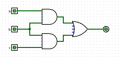
bool cool(bool a, bool b, bool c) {
	return (a && b) || (b && c);
}
Now let's look at its truth table (in a cool ASCII-ish way):
Truth Table
 a b c | S
-------+---
 0 0 0 | 0
 0 0 1 | 0
 0 1 0 | 0
 0 1 1 | 1
 1 0 0 | 0
 1 0 1 | 0
 1 1 0 | 1
 1 1 1 | 1
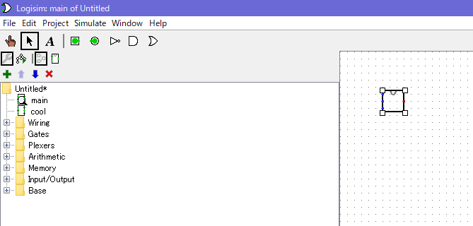
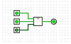
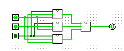
Looking at the code alone, we can also convert it to a Logisim circuit. So let's do that and start drawing spaceships in a circuiting program. Here's the twist though... Let's make it a subcircuit that we can call later on. To do this, right click anywhere in the section to the left of the program that lists Wires, Gates, etc.


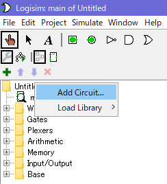
Click "Add Circuit..." and then give your new subcircuit a name (I named mine "cool", like the C++ function above). Then let's proceed with building that spaceship we were talking about earlier. Behold.


Okay that's done. Now let's go to the "main" circuit. On the left of your screen, you should see both "main" and your new subcircuit's names appear. Just double click the one you want to see. You have successfully learned how to make multiple circuits in a single Logisim project!
Using Subcircuits in other Circuits
This is where things get a little fun. From the previous section, we have written our "cool" circuit/spaceship thing... but now we want to actually use it. I'm going to assume you followed what went on in the section above and we will continue from that. Go to your "main" circuit by double clicking it. Now let's add in our "cool" circuit. single click "cool" (or whatever you named it) in the pane to the left. Then go to the grid on the right and pretend like you are trying to place down a switch. You will see that you have the subcircuit in hand and will be able to place it! It appears as a square. Should look like this:


NOTICE: There are 3 blue dots and 1 red dot. It may be hard to spot, but it's there. The blue dots are for your "input" (Notice in the previous section, we implemented "cool" to have 3 inputs), and the red dots are for your "output". You can attach wires and other things to these if you wish. Let's attach 3 inputs and one output to it.


This will now function as if it was like how our "cool" circuit operated, with the two AND gates and the OR gate. However, it is compact in to a single square. Now let's get a little crazy and chain them.


Looks crazy right? Three "cool" circuits accepting input from A, B, and C. And then the output of all three of those go into a fourth "cool" as input. Coincidentally, this circuit, as a whole, has the exact same truth table as a single "cool" circuit.

You may download this Logisim project and see it for yourself! Click here.
The Lab
You will be tasked with writing, at first, a 1-bit adder. It will accept 3 inputs and have 2 outputs. Here is the synopsis on that:

Input

  • A - Bit 1 (to be added with Bit 2)
  • B - Bit 2 (to be added with Bit 1)
  • Cin - Carry

Output

  • Sum - Bit
  • Cout - Carry
Basically, you are going to make a circuit (as a subcircuit!) that takes A, B, and Cin, and add them all together. Then you will return a bit that is either 0 or 1, and also a bit that signifies whether or not you had to carry a number over to the next place. So if I had A as "1", B as "0", and Cin as "0", then my Sum would be "1" and my Cout would be "0". Here is a truth table for you.
Truth Table
 a b Cin | Sum Cout
---------+----------
 0 0 0   | 0   0
 0 0 1   | 1   0
 0 1 0   | 1   0
 0 1 1   | 0   1
 1 0 0   | 1   0
 1 0 1   | 0   1
 1 1 0   | 0   1
 1 1 1   | 1   1

"Ok Clara, then what?"

Well let's think here, you will have a circuit that does 1 bit addition... so why not expand it to 2 bits? What about 4? Your ultimate task is to make a 4-bit added with the circuits. So you will chain 4 copies of your subcircuit in to your "main" one, and handle inputs accordingly. When it's done, you will have your own special 4-bit adder and be able to perform basic addition with it.

There is more though... you will also be expected to do two's compliment and then add subtraction to the lab. You already know that two's compliment is as simple as flipping all of the bits and then adding 1. And you also know that adding a number to a two's complimented number causes subtraction, so use that to finish this lab. Good luck!
Lab Simulator
Unfortunately, a simulator of this lab would mean showing you how the circuits are designed! Since it isn't code that I can simulate on the server-end, there is no simulator for this lab.